Chapter 5 - The ICA Family of Cards
This chapter explains how to set up a Banyan server for an option that uses a serial communications connection. It assumes that you installed an ICA-family serial card (ICA/HS™) in your server following the instructions provided in the ICA Installation Guide. This guide describes how to plan software options and line speeds for the card you installed, according to the performance guidelines given for each card. Information on assigning lines from the server is in Chapter 6.
This chapter includes the following:

An overview of each of the five cards in the ICA family and their maximum line speeds 
A brief description of how T1 and Fractional T1 are supported on the ICA family of cards 
Requirements for installing ICA cards 
Guidelines and instructions for figuring out load averages on each card, planning for performance 
A brief description of WAN Server-to-Server considerations
In this chapter, all references to ICA card refers to the ICA/HS card.
The ICA cards are high-performance serial communications cards. Each card includes a 16-bit 80286 microprocessor, an 8237 Direct Memory Access (DMA) controller, and 512 KB of dynamic RAM. Each card provides six ports, allowing it to run a maximum of six communications lines simultaneously.
The current ICA family of cards comprises the Intelligent Communications Adapter with High Speed (ICA/HS) card. The ICA/HS is a half-sized, 16-bit ISA serial communications card that can run at speeds up to 384 Kbps while using only 16 KB of memory.
The maximum line speed for each port on an ICA family card depends on the line and the protocol running on the line. In synchronous mode, lines 1 and 2 automatically use the card's DMA controller. The DMA controller offers two valuable features:

A maximum line speed of 384 Kbps 
Better throughput, because the card processes an entire frame at a time instead of a character at a time
Using the DMA controller increases card performance and reduces the load on the card. Even if you do not use line speeds greater than 19.2Kbps, you should reserve ports 1 and 2 for synchronous options. Table 5-1 summarizes the maximum line speeds for ICA family cards.
| Port Number | Type of Communications | Maximum Line Speed Supported |
| Lines 1 - 2 | Synchronous (HDLC, X.25, 3270 SNA) | 384 Kbps |
| Asynchronous Server-to-Server | 115.2 Kbps | |
|
Asynchronous Terminal Emulation or UNIX TTY |
19.2 Kbps | |
| Lines 3 - 6 | Synchronous (HDLC, X.25, 3270 SNA) | 19.2 Kbps |
| Asynchronous Server-to-Server | 38.4 Kbps | |
|
Asynchronous Terminal Emulation or UNIX TTY |
19.2 Kbps |
Lines connected to ports 1 and 2 can support Fractional T1 (FT1) communication, which allows two servers to use part of a full T1 data link to communicate. Each T1 data link is divided into 24 DS0s. Each DS0 supports a transmission speed of 64 Kbps or 56 Kbps, depending on the capabilities of your CSU/DSU. The CSU/DSU acts as the interface between the long-distance carrier and one or more FT1 lines connected to the ICAplus.
Note: You cannot connect a server running T1 Server-to-Server on a Promptus T1 card with a server running FT1 on an ICAplus card. For more information on configuring the Promptus T1 card, see the Banyan T1 Server-to-Server Guide.
A full T1 data link provides an aggregate transmission speed of 1.544Mbps. However, framing overhead consumes 8 Kbps of a full T1 data link. The actual maximum aggregate transmission speed for data is 1.536 Mbps (64 Kbps times 24 DS0s).
Because a line connected to port 1 or to port 2 supports a transmission speed of up to 384 Kbps, the line can take advantage of up to 6 DS0s (64 times 6).
Note: Throughout this document, a line that is used for FT1 communications is referred to as an FT1 line.
Typically, long-distance communications carriers offer FT1 services that provide customers with one of the following:

1 DS0 (64 Kbps) 
2 DS0s (128 Kbps) 
4 DS0s (256 Kbps) 
6 DS0s (384 Kbps) 
8 DS0s (512 Kbps) 
12 DS0s (768 Kbps)
The ICA/HS, ICA/RM, and ICAplus cards support Fractional T1 (FT1) communications. The basic ICA card and the ICAmC card do not support FT1 communications.
The ICA/HS, ICA/RM, and ICAplus cards support synchronous server-to-server communications only. The total number of FT1 lines that a single server supports is limited only by the number of cards installed in the server. For example, if you install five cards in a server, you can have up to 10 FT1 lines.
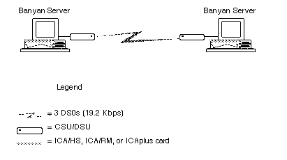
Figure 5-1 shows a Banyan network in which two servers are connected by three 19.2 Kbps DS0 circuits. Each server has a single FT1 line.
Depending on the capabilities of the CSU/DSU, you can connect more than one FT1 line to the same CSU/DSU. In this case, the following rules apply

The lines can be connected to the high-speed ports on either the same card or different cards. 
The server can use the lines connected to a CSU/DSU to communicate with the same remote server or different remote servers.
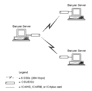
Figure 5-2 shows two FT1 lines connected to the same CSU/DSU. Each line supports six 384 Kbps DS0s. The server uses the lines to communicate with different remote servers.
Before you connect the ICA family card to the CSU/DSU, decide which role the server plays in the connection. The server can play one of the following roles:

Data Communications Equipment (DCE) 
Data Terminal Equipment (DTE)
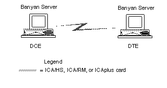
You must specify DCE or DTE when assigning the option at the server console. Coordinate with the administrator of the other server when determining the DCE/DTE roles. The role you assign to your Banyan server should be the opposite of the one assigned to the Banyan server at the other end of the connection. Figure 5-3 illustrates this.
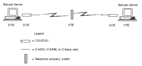
An intermediate device, such as a CSU/DSU, does not affect the roles of the servers at the endpoints. A CSU/DSU device is always a DCE. Figure 5-4 shows an example of DCE and DTE assignment when there are intermediary devices.
For information on installing an ICA card, see the Banyan ICA Installation Guide. Make sure you connect the ICA cable before you begin to assign lines.
Some of the software protocols that run on the ICA family of cards require a separately purchased option. Make sure that the software necessary to run your option is installed on the server. The option name will appear in a list of supported options on the Manage Serial Lines menu.
If you have never installed an option with an Option Code, refer to the chapter on installing Banyan options in Banyan Server Operations Guide for complete instructions.
If you are already familiar with this process, the following procedure provides a quick reference of the steps involved.
To Verify that the Option Is Installed
1. At the Operator Menu, choose Manage Communications. The Manage Communications menu appears.
2. Choose Serial Communications. The Serial Communications menu appears.
3. Choose Manage Serial Lines. The Manage Serial Lines menu appears.
The Manage Serial Lines menu lists all the serial communications options available along the top of the menu display. If the option name does not appear on the screen, you must install the option.
To Install an Option
1. From the Operator Menu, choose Shut Down Server Software.
2. From the Shut Down Menu, choose Shut down services and return console to OPERATOR MENU.
3. At the Operator Menu, choose System Maintenance.
4. At the System Maintenance menu, choose Manage Software Options. Use the menu choices to install an option with the Option Code.
5. When the Option Code software is installed, press ESC until you return to the System Maintenance menu.
6. Select Return to Operator Menu.
7. Select Restart Services from the Operator Menu.
Allocating Options to ICA Cards
You can allocate more than one option to an ICA card. By planning which options you place on which lines, you can optimize the ICA card's performance. Whenever you add an option to an ICA card, use the performance guidelines discussed in this section. These guidelines help you distribute options among the card's available ports.
Card performance is a function of several factors, including card hardware characteristics, option software characteristics, and the line speeds you use. The sections that follow describe these card and option characteristics and provide guidelines for arranging options on the card.
Port describes the hardware connector on the card. Line describes how the port is used.
The six ports on an ICA card are labeled line 1 to line 6. The software line numbers associated with each port are referred to as s-p, where:
s is the server slot number in which the card is installed.
p is the port number.
For example, the software line numbers 5-1, 5-2, 5-3, 5-4, 5-5, and 5-6 represent the six ports on an ICA card installed in slot 5.
Figure 5-5 shows ports on the connector for an ICA card.
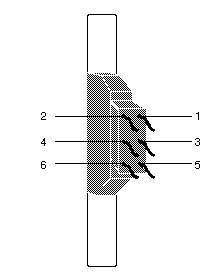
If you are not sure which port is which, look at any of the six connectors on the ends of the wires extending from the connector that plugs into the server. Each connector is labeled with the line number. For example, the connector for line 1 will be labeled LINE 1, the connector for line 2 will be labeled LINE 2, and so on.
The Manage Serial Lines menu at the server console provides a list of all lines available on the server and the options currently assigned to each one. Chapter 6 describes this menu in detail.
Lines on the ICA card are prioritized in descending order. Line 1 has the highest priority and line 6 the lowest. When all lines operate at the same time, the card's processor services each line in the order of its priority. As a general rule, you should assign lower-speed lines to lower-priority line numbers, because they require less processing than high-speed lines.
This section describes how to calculate the total load capacity of an ICA-family card. The load placed on the card at any one time by the active options should not exceed 100 percent.
As the load exceeds maximum capacity, the processor on the card can become too busy and cause one or more characters to be lost. The VINES Network System Management (VNSM) tool can tell you if characters are transmitted or received improperly. For more information on VNSM, see Monitoring and Optimizing Servers.
Most protocols re-transmit on an error so that no data is lost. However, the extra re-transmissions can result in a heavier load on the card, causing a loss in performance. For UNIX TTY or the Asynchronous Terminal Emulation option, you can lose characters by overloading the card, because its protocol has no re-transmission capability.
The sections that follow explain how to calculate the load for each option and how to adjust the total load for best performance.
Determining the Load on the Card
The load on an ICA card is affected by the following considerations:

Whether or not the card uses its the high-speed lines. Lines 1 and 2, the high-speed lines, use the DMA controller. The card load decreases if the card can use its DMA controller, because the DMA controller can receive a block of information and pass it to the 80286 processor, instead of having the 80286 process every character as it is transmitted and received. DMA is available on ports 1 and 2 of the card. 
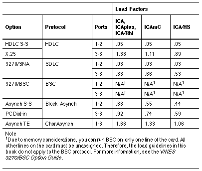
The load factor associated with each option. Each protocol requires a certain amount of processing overhead. Table 5-2, which follows, lists these load factors. 
The line speeds the options use. Calculate the load value on a line by multiplying the option's load factor by the line speed you use. The higher the line speed, the more load you place on the card's processor. 
The number of active lines that operate at the same time. After you determine a load value for each line on the card, add the load values of all lines that will operate at the same time. For example, if you have a server-to-server asynchronous line that runs only at night, and the rest of the lines run only during the day, the total should include all lines except the server-to-server asynchronous line. The resulting number represents the maximum load placed on the card at any one time.
Table 5-2 lists the load factors assigned to each option for the ICA family of cards. The table includes two load factors for all options except Asynchronous Terminal Emulation. For each option, the table gives one set of factors for the two high speed ports (ports 1 and 2) and another set for ports 3 through 6. The load factors in the table are expressed as a percentage per Kbps of the total load on the card.
For each line you want to use, fill in the corresponding line on the worksheet provided in Appendix A as described in "To Calculate the Load on a Card," which follows.
To Calculate the Load on a Card
1. Write the line number in the Line # column on the worksheet.
2. Write the option name in the Option Name column. Remember, if you have synchronous options, assign them to lines 1 and 2 for best performance.
3. If the line will be active, write Y or N in the Active Line? column.
4. Use Table 5-2 to look up the load factor associated with the option for that line.
5. Write the load factor in the Load Factor column.
6. Choose the line speed for the line, referring to Table 5-1 if necessary, for the maximum speed allowed.
7. Write the line speed in the Line Speed column.
8. Calculate the line load by multiplying the load factor value by the line speed value.
9. Write the result in the Load column.
Repeat these steps for each line. When you have entered the information for all lines:
1. Add the values in the Load column for all lines that will be active at the same time.
2. Write the result in the space provided for Total Load at the bottom of the worksheet.
If your Total Load value exceeds 100 percent, make some adjustments to the options on the card, as described in "Adjusting the Load on the Card," which follows.
Adjusting the Load on the Card
If the total load exceeds 100 percent, you need to make some adjustments or remove one of the options from the card. Suggestions for possible adjustments are:

If you have more than two options that run synchronous protocols, make sure the ones with the highest load factors or line speeds are assigned to ports 1 and 2. 
If you reduce the line speed for one or more options, you may still be able to run all the options you want on the card. Reducing one line speed can sometimes reduce the total load considerably. 
If the server includes more than one ICA card, balance options by distributing the number of active lines or by distributing options with very high and very low load factors among the available cards.
If you exceed 100 percent by just a small amount, you may experience performance problems only occasionally. The calculations in this chapter assume everything is running simultaneously. For full-duplex HDLC, the load factor assumes simultaneous transmissions in both directions. However, in practice, an HDLC line does not always transmit in both directions at the same time.
Card Load Examples
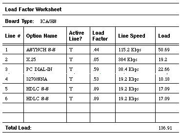
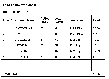
Figure 5-6, Figure 5-7, and Figure 5-8 show sample worksheets with combinations of different options and line speeds on two different types of ICA cards. Each example includes a value for the total load on the card, based on the load factors and line speeds of the active lines on the card.
Example Adjusting the Load on an ICA/HS Card with Five Options
The worksheet sample in Figure 5-6 shows five options distributed over six lines. If the administrator uses the maximum line speed allowed for each port and makes ever line active, the total load on the card is 136.91 percent of the maximum load allowable on the ICA/HS card. This load exceeds maximum capacity.
The administrator has to rebalance the load on the card. Since Asynchronous Server-to-Server has the highest load (50.69 percent of capacity), the administrator could make the largest reduction in load simply by reducing the speed of this line. In this example, though, the administrator has decided that the Asynchronous Server-to-Server option must run as fast as possible.
Another way to reduce the load is to disable lines, since the total load depends on which lines are being used concurrently. However, even if the administrator disables lines 5 and 6, the HDLC Server-to-Server lines, the total load on the card is still 102.73 percent.
After considering all the possibilities, the administrator made the following changes to reduce the load on the card:

Reduced the line speed for line 2 (X.25) to 115.2 Kbps. 
Reduced the line speed for line 3 (PC Dial-in) to 19.2 Kbps. 
Disabled line 6, the second HDLC Server-to-Server line.
Figure 5-7 shows the same worksheet with the new values.
Example Adjusting the Load on an ICA/HS Card with the Asynchronous Terminal Emulation Option
The card described in the worksheet sample in Figure 5-8 uses the Asynchronous Terminal Emulation option on all six lines. The Asynchronous Terminal Emulation is limited to a maximum speed of 19.2Kbps regardless of the line to which it is assigned.
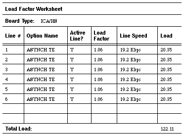
If the administrator runs all six lines at the maximum speed, the total is 122.11 percent, which is more than the capacity of the card. To reduce the load, the administrator can reduce the speed on some of the lines, disable some of the lines, or use a combination of both methods.
If you do overload the card by a small amount, it is important to understand and to plan for performance problems.
The protocols for all options except the Asynchronous Terminal Emulation option re-transmit on errors. At worst, overloading the card degrades performance. The card must keep up with normal processing and also handle the extra transmissions to transmit and receive data correctly.
If all lines are busy, an initial performance problem can grow increasingly worse as retransmissions occur on more and more lines due to the lack of adequate processor time.
The protocol for the Asynchronous Terminal Emulation option cannot retransmit characters on an error. If the card begins to experience performance problems, you can lose data. Users may notice that they are losing some characters. This situation is more likely to happen when the option is using the lowest-priority ICA lines (5 and 6), because the processor services these lines last.
One corrective action you can take, aside from reducing the load on the card, is to assign this option to a higher-priority line. The VINES Network Systems Management tool can help you track performance problems. For more information on tracking performance problems with VNSM, see Monitoring and Optimizing Servers.
The load guidelines described provide all the requirements to use the ICA card effectively. You now can begin connecting lines to the card as described in Chapter 6.
After you connect a line to a server port, you must make the line available to the Banyan networking software by assigning the line at the server console. See Chapter 6 for instructions on assigning lines.
If the line uses a modem, be familiar with the features and capabilities of the modem. For example, what speeds does the modem support? Does the modem support the Hayes command set? Does the modem use the PEP protocol? Does the modem use compression? If possible, have the modem documentation available when you configure the line for the modem. For information on modem scripting, see the Modem Scripting Guide.