Chapter 5 - VINES Optional Services
VINES Optional Service Descriptions
Banyan provides a variety of optional services and features that accommodate a wide range of networking requirements. See Chapter 4 for a detailed discussion of how services and clients interact in the VINES environment.
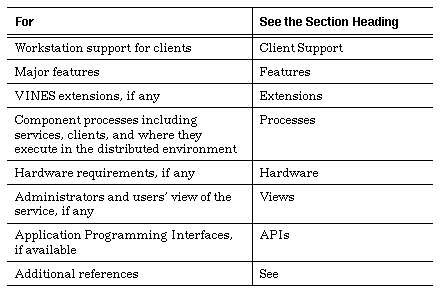
The sections that follow present information about each VINES optional service. Table 5-1 lists the information included in each entry.
Description The 3270/BSC service provides workstation users with IBM-compatible, fully featured, 3270/BSC terminal emulation.
Client Support DOS workstations.
Features The service emulates a 3274 Model x1C controller. The product supports both Type 1 (SNA character string) and Type 3 (3270 Data Stream) printers by emulating 3287 Model 1 and 2 devices.
The workstation emulates a 3278 or 3279 Model 2B display station. Workstations can engage in up to four concurrent sessions, with a maximum of one print session. Support for workstation display adapters includes:

Standard monochrome 
CGA 
EGA 
Host Session Adapter (3270/PC)
Extensions The 3270/BSC service also provides device access control based on VINES StreetTalk names. Special files loaded before entering emulation let the user or administrator:

Redefine keyboard functions. 
Modify the translation of extended character attributes sent from the host.
Other features include:

File transfer 
Data capture to disk or printer during emulation sessions 
Hotkey to enter and exit emulation
Processes The 3270/BSC service runs on the server and uses a serial communications port or a Token-Ring card to connect to the host. Administrators use a workstation management client to configure the service. Two other clients manage keyboard definition files and graphics adapter files.
For terminal emulation, there are two DOS clients. The resident client provides a programmatic interface to the service. The transient client provides a VINES interface between the user and the resident client.
Hardware Use a serial communications card and a serial line connected to a modem, or modem eliminator to connect to the host. You can also use a Token-Ring card to connect to the host.
Views Administrators configure the service to conform to host and server requirements, set access rights to devices, and so on. Administrators configure VINES user profiles to:

Set up default mappings that associate users or groups with a service. 
Specify parameters to control interaction with the host.
The user's workstation acts as a supported IBM terminal, with optional keyboard definitions, display attribute translation, disk capture of print data, and a hotkey to enter and exit from emulation.
All or part of the workstation emulation client can be made resident, providing an exit to DOS while in session with the host, which is useful for file transfers or temporary exit to perform DOS tasks.
Users can enter emulation from the DOS command line, specifying parameters to choose a service, devices, and other settings. All user capabilities are subject to administrator-controlled access rights.
APIs Third-party applications can interface to the resident client using DOS calls to the VINES interrupt vector. A list of supported calls is provided in the VINES Programmer's Interface (DOS).
See VINES 3270/BSC Option Guide and VINES Programmer's Interface (DOS).
Description The 3270/SNA service provides workstation users with IBM-compatible, fully featured 3270/SNA terminal emulation.
Client Support DOS workstations.
Features The service emulates a 3274 Model x1C controller. The product supports both Type 1 (SCS) and Type 3 (DSC) printers by emulating 3287 Model 1 and 2 devices.
The workstation emulates a 3278 or 3279 Model 2B display station. Workstations engage in up to four concurrent sessions, with a maximum of one print session. Support for workstation display adapters includes:

Standard monochrome 
CGA 
EGA 
Host Session Adapter (3270/PC)
The client software provides full support for the 3270/PC keyboard.
Extensions 3270/SNA lets administrators restrict access to logical units based on VINES StreetTalk names. Special files loaded before entering emulation let the user or administrator:

Redefine keyboard functions. 
Modify the translation of extended character attributes sent from the host.
Other features include:

File transfer 
Data capture to disk or printer during emulation sessions 
Hotkey to enter and exit emulation
Processes The 3270/SNA service runs on the server and uses a serial communications port to connect to the host. Administrators use a workstation management client to configure the service. Two other clients manage keyboard definition files and graphics adapter files.
For terminal emulation, there are two DOS clients:

The resident client provides a programmatic interface to the service. 
The transient client provides a VINES interface between the user and the resident client.
Hardware Use a serial communications card and a serial line connected to a modem or modem eliminator.
Views Administrators configure the service to conform to host and server requirements, set access rights to devices, and so on. Administrators configure VINES user profiles to:

Set up default mappings that associate users or groups with a service. 
Specify parameters to control interaction with the host.
The user's workstation acts as a supported IBM terminal, with optional keyboard definitions, display attribute translation, disk capture of print data, and a hotkey to enter and exit from emulation.
All or part of the workstation emulation client can be made resident. This provides an exit to DOS while in session with the host, which is useful for file transfers or temporary exit to perform DOS tasks.
Users enter emulation from VINES menus or use the DOS command line to specify a service, logical units, and related options. All user capabilities are subject to administrator-controlled access rights.
APIs Third-party applications can interface with the resident client through DOS calls to the VINES interrupt vector. This API allows full access to the LU 2 data stream. A list of supported calls is provided in the VINES Programmer's Interface (DOS).
See VINES 3270/BSC Option Guide and VINES Programmer's Interface (DOS).
Asynchronous Terminal Emulation (ATE)
Description The Asynchronous Terminal Emulation (ATE) option lets network workstations emulate asynchronous terminals and access remote hosts through serial lines.
Client Support DOS workstations.
Features ATE supports standard terminals including:

VT100 
VT5 
IBM 310 
TT
It can support additional types of terminals if Int 14/6B is used. Int 14/6B lets third-party ATE clients use Banyan's ATE service.
Extensions Administrators control access to host connections based on VINES StreetTalk names. The service also provides:

Modem pooling to multiple hosts (including auto-dial) 
Kermit file transfer 
ASCII file transfer 
Data capture to disk or printer during emulation sessions
Users access hosts through administrator-configured connection names, parameter files, and/or script files. VINES menus, parameter files, and script files control settings for:

Data capture 
File transfer 
Communications 
Terminal type
Processes The ATE service runs on the server, using serial communications ports with or without auto-dial modems. Kermit file transfer software runs under UNIX on the server.
A service-specific management client running on workstations lets administrators set up and control access to named connections to host computers.
The resident and transient emulation clients lets users:

Load parameter files. 
Save and change settings for data capture. 
Perform file transfers. 
Control communication settings. 
Select terminal type. 
Execute script files from the workstation.
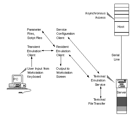
Figure 5-1 shows how the component processes of Asynchronous Terminal Emulation interact.
Hardware The service uses a serial communications card and one or more serial lines in the server. Modems and phone lines are required to connect to remote hosts.
Views Administrators configure the service with one or more connection names. Connection names include information conforming to host and server requirements. Administrators configure VINES user profiles to:

Set up default mappings that associate users or groups with a service. 
Point to a DOS directory that contains parameter and script files, which control emulation settings and interaction with the host.
VINES terminal emulation screens let administrators change terminal or communications settings and specify a protocol type and a file name for a file transfer operation. Administrators can save settings in DOS parameter files and provide them to users through VINES menus.
The workstation acts as a supported asynchronous terminal. One of the workstation emulation clients can be made resident, providing an exit to DOS while in session with the host.
Users enter emulation through VINES menus or the DOS command line, selecting a connection or parameter file or dialing out manually from the emulation screens. Use of dial-out and connection names is subject to administrator-controlled access rights.
The VINES terminal emulation screens lets users:

Change terminal or communications settings. 
Enter a protocol type and a filename for a file transfer operation. 
Save settings to DOS parameter files for later use.
APIs Third-party applications interface to the resident client using DOS calls to the VINES interrupt vector for direct asynchronous access or through the Int 14h/6bh interface. A list of supported calls is provided in the VINES Programmer's Interface (DOS).
See VINES Asynchronous Terminal Emulation Guide and VINES Programmer's Interface (DOS).
Description The Intelligent Messaging option provides mailbox functions to local users and transfers messages to distant users.
Client Support DOS, OS/2, Windows, and Macintosh workstations.
Features When a user sends a message, the transfer agent of the mail service specified in the user's profile resolves all the addresses associated with the message. Addresses can be StreetTalk names, list names, nicknames, patterns, or remote addresses, such as Remote Electronic Mail Address (REMA) addresses. To resolve an address, the transfer agent determines the destination transfer agent to which it will transport the message, so that the message can be ultimately delivered to a recipient.
Once an address is resolved, the transfer agent transports the message in one of two ways. If the recipient's mailbox is:

Maintained on the local server - The transfer agent delivers the message to the mailbox. 
Stored on another server - The transfer agent transports the message to the destination transfer agent.
The process of resolving addresses and transporting messages is multi-threaded. Multi-threaded processing lets the transfer agent simultaneously process multiple messages. Multi-threaded processing allows messages that may be resolved and transported easily to be delivered while the transfer agent continues to work on difficult messages.
Example Processing Messages to Local and Remote Destinations
A message is addressed to two individuals:

Jeff Davis, whose mailbox is maintained on the local mail service 
Susan Santiago, whose mailbox is maintained on a remote mail service over a slow link
The transfer agent resolves and delivers the message to Jeff Davis while it processes the delivery of the message to Susan Santiago.
Message Queues To accomplish multi-threaded processing, the mail service uses multiple queues, visible as special mail folders. Each queue is a directory on the server that the mail service uses to store messages being processed by specific tasks. Messages in a queue are distinguished from one another by their message IDs.
The following types of queues are used by Intelligent Messaging:

All messages that a mail service receives from other mail services are initially received in the Accept queue. These messages reside here until they are moved into the first Resolve queue. 
All messages that a mail service receives from local network users are initially received in the Send queue. These messages reside here until they are moved into the first Resolve queue. 
The transfer agent uses three Resolve queues to process the StreetTalk names of message recipients. Within each Resolve queue the transfer agent works to resolve the recipient name for a specified amount of time. When the time limit elapses, the transfer agent moves on to the next message. The unresolved message is transferred to the next level Resolve queue. 
The transfer agent uses three Transfer queues. The transfer agent uses network routing information to determine the network cost of transferring each message, based on the line speed between local and destination mail services. Once the cost is determined, the transfer agent moves the message into one of the other Transfer queues, depending on its cost.
Message Compression The mail service uses a compression utility to compress messages. The mail service compresses a message when the message and its attachments combined are 5 KB or greater. By compressing only large messages, small messages are transferred quickly, rather than consuming time and resources to compress them.
Checkpointing Intelligent Messaging uses checkpointing to transfer messages over transient links. Checkpointing lets the destination mail service recover partially transferred messages and attachments when the transfer of the message over the link is interrupted. When the link becomes available again, the source mail service continues the transfer, starting with the next block in the message rather than initiating the transfer again at the first block.
Service Statistics Mail service logs contain information on system and service activity, including transport statistics. This information is useful in a variety of situations, such as troubleshooting, diagnosing problems, and measuring usage.
Processes On the server, three components provide Intelligent Messaging services, as follows:

The mail service provides mailbox services to the workstation client, including:
- Creating
- Deleting
- Sending
- Organizing messagesWhen a user runs the client at a workstation, the corresponding mail service, specified in the user profile, lets the user access a mailbox.

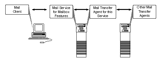
The transfer agent, on the same server, provides two-way message transfer between the local mail service and other transfer agents, including mail gateways and standard transfer agents. 
The janitor service empties all the Wastebasket folders at a specified time every day. Even when Wastebaskets are empty, the deleted mail messages consume disk space until approximately two janitor cycles elapse. At that time, the deleted mail messages are completely removed from the disk.
Figure 5-2 shows the relationship between the mail client, service, and transfer agent.
Views Using a mail management client process, administrators can:

View the current users of a service. 
Control the allowable maximum number of messages in a user mailbox. 
Empty a mailbox. 
Set limits on the use of templates or wildcards to send or receive mass mailings. 
Disable a mailbox. 
Move a mailbox to another service. 
Monitor the total number of messages a mailbox contains.
Intelligent Messaging is fully integrated with the VINES backup/restore mechanism.
Intelligent Messaging is a PC-style application program with its own text editor. In most cases, the user needs to know only the StreetTalk names of addressees. Each user also has a personal address book that provides quick access to frequently used StreetTalk or remote addresses, in addition to the standard StreetTalk catalog.
APIs The VINES Applications Toolkit contains a full set of APIs for developing applications that use Intelligent Messaging either as a client of the mail service (Mail Client API) or as a gateway between foreign mail systems and Intelligent Messaging (Intelligent Messaging Gateway APIs).
See Intelligent Messaging Administrator's Guide, Intelligent Messaging User's Guide, VINES Mail Client Programming Interface, and VINES Mail Gateway Programming Interface.
Description The Macintosh options let you connect Macintosh computers and other devices (for example, PAP-compatible PostScript printers) that have built-in support for AppleTalk protocols to a VINES network. Macintosh options include support for:

The AppleTalk Filing Protocol (AFP) and AppleTalk Routing 
The VINES Mail for Macintosh option, which additionally provides support for VINES mail 
The Banyan AppleTalk Agent, which supports applications created using VINES IP
Client Support Macintosh workstations.
Features VINES servers support AppleTalk Phase 1 and AppleTalk Phase 2. Apple Computer recommends that you use Phase 2. VINES 5.x can also operate with other AppleTalk routers such as the Apple Internet Router, the Shiva FastPathTM router, and the Cayman® GatorBox® router.
Since AppleTalk protocols run on a VINES network, your network is not limited to Macintosh workstations; the same LAN segments can also include DOS workstations and OS/2 workstations. Appletalk protocols reside in their own stack in the server alongside the VINES protocol stack. This allows traffic from Macintosh and DOS-based workstations to use the same physical media to communicate with the same server.
AFP On a VINES network, AFP is implemented as a service on the server, allowing the VINES server to function as an AppleShare file server. AFP runs in addition to the VINES File services that run on the server. Both VINES AFP and AppleShare use the AppleTalk protocols as a base.
In addition to handling file sharing, the VINES AFP service maps DOS filename extensions to Macintosh file types and file creators. It also passes login information to and receives authentication from the VINES Security Service.
ATA The Banyan AppleTalk Agent (ATA) provides support for Macintosh clients built with the VINES Applications Developer's Toolkit. ATA accepts socket calls from the Macintosh client using ASP. It then issues the same call using VINES socket calls, such as VnsOpenSocket. In this way, Macintosh clients can interact with VINES applications that use VINES IP.
Tunneling Using tunneling, Macintosh workstations on your network can communicate across servers that may not be running the VINES option for Macintosh. Tunneling means that servers that are not configured for the AppleTalk protocol can still forward AppleTalk information received from one server to other servers on the network, but cannot accept any information from or provide any information to Macintosh workstations.
VINES packet headers make encapsulation, or tunneling, possible. Tunneling lets AppleTalk packets travel over a VINES network, through servers that are not running the AppleTalk protocol. The AppleTalk packets are wrapped, or encapsulated, in VINES headers. To the rest of the VINES network, they appear as normal VINES packets. The Banyan TCP/IP Routing option performs similar tunneling on VINES networks.
Printer Support VINES 5.x supports the Apple LaserWriter® printer and other Printer Access Protocol (PAP)-compatible PostScript printers. The printer must be attached to a network cable (LocalTalk, Ethernet, or Token-Ring) and cannot be directly attached to the serial or parallel ports of a server.
Processes AppleTalk protocols let AppleTalk-compatible devices communicate over a VINES network. A VINES server on which the AppleTalk software is configured can communicate with Macintosh workstations anywhere on the network, provided that all intermediary media can support AppleTalk or that tunneling is in use.
AppleTalk protocols reside in the VINES kernel, along with other protocol families like TCP/IP. A protocol's layers are sometimes collectively referred to as a protocol stack. The AppleTalk stack remains inactive on the server until AppleTalk is configured and the AppleTalk software is started from the server console. Once the software is started, AppleTalk packets received by the server are delivered to the AppleTalk Datagram Delivery Protocol (DDP) for handling.
AFP is implemented as a service on the server, letting the VINES server function as an AppleShare file server.
Hardware With VINES 5.x, all supported Ethernet, StarLAN, Token-Ring, and LocalTalk cards can be used for AppleTalk communications. All but the LocalTalk card can support multiple protocols (such as VINES and TCP/IP) concurrently.
VINES supports LocalTalk cabling. However, to reach the non-extended maximum of 254 nodes using LocalTalk cabling, you need separate networks, or LAN segments, connected to an internet router.
You can have both Phase 1 nodes and Phase 2 nodes in the same network. However, they are restricted to non-extended addressing. The VINES server does not support both Phase 1 and Phase 2 concurrently. One or more transition bridges are additionally required. By using tunnelling, you can configure a Phase 1 VINES server to communicate with a Phase 2 VINES server.
The Apple Personal LaserWriter LS uses a serial interface. Other Apple LaserWriter printers use LocalTalk cabling, which lets them connect to a network. You can connect a LocalTalk LAN segment to a server using a DaynaTALKTM card. The LAN segment can support Macintosh workstations as well as the printer.
Views Administrators configure Macintosh options using the AppleTalk configuration menus. These menus, accessed from the server console, let you:

Start and stop AppleTalk communications 
Manage AppleTalk ports 
Change AppleTalk phases 
Manage routing of AppleTalk packets through a VINES network 
Display port status 
Display routes
Macintosh users access VINES file services by selecting the name of the file service in the Macintosh Chooser menu instead of selecting a drive designator. File services are mounted on the user's desktop and adhere to standard Macintosh conventions.
The user interface of the VINES Mail Option for Macintosh conforms to Macintosh interface guidelines. The option lets you read, compose, send, and file mail messages.
APIs The VINES Applications Toolkit provides Macintosh-specific APIs that let you build client applications that interact with VINES and VINES-compatible third-party applications.
Description The PC Dial-in option lets workstations connect to a server using a block-oriented asynchronous protocol.
Client Support DOS workstations.
Features The Dial-in option lets users set up a telephone connection between a user's workstation and a VINES server in order to log into the network.
Security Users who can access your server have access to your entire network. You can create a User Dial-in Access List on the server to limit the dial-in access.
Dial-in Scripts PC dial-in provides a scripting facility that lets you support the modem type of your choice and an intermediate switching device such as a PBS or a PAD.
Hardware The server must contain a serial communications card. The modem connections to the server use standard RS232 cables.
Views The VINES PCCONFIG programs controls the configuration of options at the workstation level.
APIs None.
See PC Dial-in Guide.
Server-to-Server SNA
Description The Server-to-Server SNA option (SS/SNA) lets you connect VINES networks over a local or wide area SNA network.
Client Support No application client resident on network workstations.
Features The SS/SNA lets VINES network traffic run on an IBM SNA backbone network. SS/SNA makes all services on a local VINES network available on a remote VINES network located across an SNA network. Figure 5-3 shows a sample SS/SNA network.
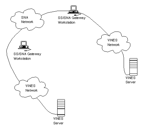
The option runs on a VINES server and requires a dedicated gateway workstation that serves as an SNA gateway. No additional software is installed on the SNA host systems.
SS/SNA provides the following features:

Configuration and operation from any VINES client 
Full support for the VINES Access Rights List (ARL) 
Collection of traffic statistics 
Support for up to 1 logical connections to other SS/SNA services running elsewhere in the network
Processes The gateway communicates over the SNA network using IBM's Advanced Program-to-Program Communications protocol (APPC/PC). The gateway supports traditional SDLC data links as well as IBM Token-Ring facilities.
SS/SNA uses the peer-to-peer communications capabilities defined within SNA. SS/SNA participates in the SNA network as a Physical Unit (PU) type 2.1, supporting an independent logical unit.
Hardware The gateway workstation must meet the following minimum requirements:

286-based 
640 KB RAM 
10 MB hard drive
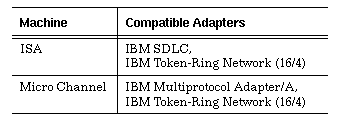
Table 5-2 lists the adapters you can use to connect ISA and Micro Channel machines.
Views Administrators perform the following tasks:

Install the service on the server. 
Configure the service on the server console using the Manage Communications screen. 
Add and configure the service using the VINES MSERVICE command. 
Make the service available to users.
APIs None.
See VINES SS/SNA Guide.
Server-to-Server Wide Area Network (SS/WAN)
Description The Server-to-Server Wide Area Network (SS/WAN) option lets you create wide area networks by connecting VINES servers.
Client Support No application client resident on network workstations.
Features The SS/WAN lets you connect two VINES servers. Servers can be connected in one of the following ways:

Synchronous direct-connect lines 
Synchronous dial-up lines using HDLC 
Asynchronous direct connect lines using block-oriented asynchronous protocols 
Asynchronous dial-up lines using block-oriented asynchronous protocols
Synchronous SS/WAN Synchronous server-to-server connections use the HDLC protocol. Figure 5-4 shows two VINES servers connected over a leased line. Each end of the leased line connects to a modem. An RS232 cable connects each modem to a VINES server. The synchronous protocol requires synchronous modems or synchronous modem eliminators.
It does not matter which server is assigned as the Data Circuit-Terminating Equipment (DCE) or the Data Terminal Equipment (DTE) as long as both servers are not assigned the same role. Coordinate the assignments with the administrator of the other server.
You can assign a line speed of up to 38.4 Kbps to the connection depending on the type of ICA card you installed. Both servers must use the same line speed.
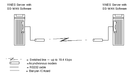
A synchronous modem eliminator is used instead of two synchronous modems to provide the clocking signal necessary for transmission. To the servers, the synchronous modem eliminator is equivalent to a pair of synchronous modems. This configuration connects servers to each other over short distances.
Using dedicated lines, the connection is available after you assign the line on both servers. If the cable is removed and then restored, the servers re-connect automatically, as long as the line assignments did not change.
Asynchronous SS/WAN The SS/WAN option also supports asynchronous server-to-server
connections. These connections use block-oriented asynchronous
protocol. Figure 5-5 shows asynchronous server-to-server connections.
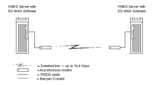
You can assign a line speed of up to 19.2 Kbps to the connection. The modems at both servers must have compatible line speeds.
Processes The SS/WAN software option must be installed in the servers to support the HDLC server-to-server protocol or block-oriented asynchronous protocol.
Hardware Hardware required depends on the type of server-to-server connection you use:

Synchronous connections typically require synchronous modems or a synchronous modem eliminator. Auto dialing is supported when using a Hayes® Smartmodem 2400TM or compatible modem. 
Asynchronous connections require two asynchronous modems, an asynchronous modem eliminator, or a null-modem cable
Views Administrators perform the following tasks:

Install the service on the server. 
Configure the service on the server console using the Manage Communications screen. 
Add and configure the service using the VINES MSERVICE command. 
Make the service available to users.
APIs None.
Simple Mail Transfer Protocol (SMTP) Gateway
Description The Simple Mail Transfer Protocol (SMTP) Gateway option provides a set of rules and procedures for transferring electronic mail, most commonly used in computer networks that support TCP/IP protocols. Typically, SMTP is used to transfer mail to networks in other organizations.
SMTP requires the TCP/IP routing option. Install TCP/IP before you install SMTP.
Client Support No application client resident on network workstations.
Features When VINES users send mail through networks like Internet, the mail can be forwarded by many mail gateways, depending on where the recipients and their computers are located.
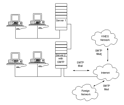
Servers that run SMTP let users on VINES network exchange SMTP mail message with users on foreign networks. For example, Figure 5-6 shows how SMTP mail passes between two VINES networks and a foreign network through Internet.
A server that runs SMTP acts as a mail transfer point between a VINES network and a foreign network, thereby limiting the server's role as a mail router. Users on foreign networks can use the server to forward mail to VINES users only.
SMPT Addresses SMTP mail uses the Remote Electronic Mail Address (REMA) format. This format includes the StreetTalk name of the SMTP service on the gateway server.
Views Administrators perform the following tasks:

Install the service on the service. 
Create domain names using the Operator Menu on the server console to access the Manage Communications screen. 
Add and configure the service using the VINES MSERVICE command. 
Make the service available to users.
Users access the service by including the address of the SMTP gateway in mail addresses. Since the address is long, you can simplify the process by creating a nickname for the service or adding the full address to users'address book.
APIs None.
See VINES SMTP Gateway Option Guide.
Simple Network Managment Protocol (SNMP) Agent
Description The Simple Network Managment Protocol (SNMP) Agent option lets a VINES server run an SNMP service. The SNMP service responds to requests from an SNMP manager and collects statistics and configuration information about a VINES network.
Client Support SNMP managers, available from third-party developers, reside on a variety of workstations.
Features An SNMP service collects informational items, such as statistics and configuration information, about the server's VINES network. It does this upon request from an SNMP manager. The service passes these items to the manager over the network. The manager displays these statistics to network management personnel or stores them. In most cases, an SNMP manager runs on workstations. SNMP version 1.1 runs over VINES, AppleTalk, NetWare, and TCP/IP networks.
The VINES implementation of SNMP takes a proxy agent approach to collecting data. The server that runs the SNMP service is the proxy agent. The servers from which data is collected are target servers. Upon request from a manager, the proxy agent collects informational items from both target servers in the VINES network. The target servers do not require the SNMP agent, but do require the VINES Network and Systems Management option. In effect, the proxy agent acts as a network management gateway between target servers and the SNMP manager, as shown in Figure 5-7.
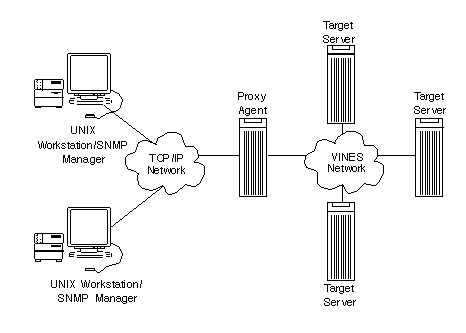
Processes To pass informational items to the SNMP manager, the proxy agent typically uses TCP/IP protocols.
To collect information, the proxy agent uses VINES communication protocols to query the VINES network management services on target servers. To collect informational items from its own server, the proxy agent queries its own VINES network management service.
Views Administrators create, add, and configure the services using the VINES MSERVICE command. The information gathered by the SNMP agent is displayed to the administer through a third-party network management application.
APIs Third-party developers can develop a standard SNMP manager. This manager calls Banyan's SNMP manager using standard SNMP commands.
See Server Agent Guide.
Description The T1 Server-to-Server option provides long-distance, high-speed, reliable transmission of data between servers.
Client Support There is no application client resident on network workstations.
Features Installing the T1 Server-to-Server software and a Promptus® T1 card in Banyan servers lets the servers connect directly to a public telephone network to provide full or fractional T1 service.
The option lets servers use each of the 24 T1 channels available - 56 or 64 Kbps capacity per channel - as a single, high-speed communications link with any other server that is also equipped with this option.
Full T1 service provides use of the whole line; that is, all 24 channels and the maximum data rate of 1.536 Mbps.
Fractional T1 service, as the term implies, provides only a smaller portion of the line. Each portion, or fraction, is allocated in 64 Kbps increments. This allocation means that the rate of transmission is correspondingly less.
The Promptus T1 card contains a built-in Channel Service Unit/Data Service Unit (CSU/DSU) so no separate CSU or DSU is required. CSU/DSU manages and encodes the digital information passed from the line to the card. It may collect statistics on line traffic.
If you already have an external CSU in place, you can use a Promptus T1 card that has only a DSU. This type of card lets you establish a type of interface called Digital Specification X-1 (DSX-1) to a local device, such as:

Another Promptus T-1 card (either with a CSU/DSU or DSU-only and an external CSU) 
A fiber optic interface 
A Token-Ring Interface Coupler (TIC) 
A T2 or T3 multiplexer 
A Digital Cross Connect Unit
You can also choose a DSU-only card interface for use in a private network if you do not need to connect to a public service provider. For example, if you use a cable strung between buildings or a direct, point-to-point connection between servers.
Processes The T1 Server-to-Server option supports Link Access Protocol D (LAPD). Servers use LAPD to communicate on T1 lines. Firmware on the T1 card formats the flag, address, control and frame check headers, while a VINES T1 device drivers formats the SNAP header and passes the header and users data to the T1 card.
Hardware This option requires any ISA-compatible computer operating at a bus speed of less than 10Mhz (typically, 8Mhz) and a Promptus T1 card (CSU/DSU or DSU-only model).
APIs None.
See Banyan T1 Server-to-Server Guide, Monitoring and Optimizing Servers, and VINES Protocol Definition.
Description The TCP/IP Routing option lets VINES servers operate in networks that use Transmission Control Protocol/Internet Protocol (TCP/IP).
Client Support No application client resident on network workstations.
Features ` This option lets the server route IP packets addressed to foreign hosts and foreign host gateways in an IP network environment. It also lets you configure other servers in the VINES cloud as gateways to IP networks, if the Routing option is installed. Thus, TCP/IP Routing makes it possible to route IP packets across a VINES network.
Without TCP/IP Routing, a server can only deliver packets to its own interface addresses; it cannot forward them to another server.
Figure 5-8 shows a sample network that includes:

Two VINES servers equipped with the TCP/IP Routing option 
Workstations running VINES 
One workstation running PC/TCP from FTP Software, Inc. 
Foreign hosts

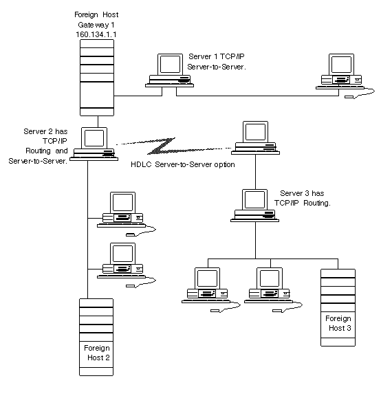
In Figure 5-8, Server 1 routes traffic traveling between Foreign Host 1, Foreign Host 2, and Foreign Host 3. Server 3 routes IP traffic between Foreign Host 2 and Foreign Host 3.
In a TCP/IP environment, VINES servers and workstations that communicate without passing packets through a foreign host gateway form a VINES network. They communicate using VINES IP.
Encapsulating Packets When IP packets travel through a VINES network, servers equipped with TCP/IP Routing encapsulate them in VINES IP headers. This lets servers route the packets through the VINES network by means of VINES IP.
The encapsulated IP packets travel over the IP backbone when they pass through the VINES network. VINES IP on each server on the backbone handles the routing. IP views the VINES network as another network interface that it passes packets to and receives packets from.
When a server has TCP/IP Routing installed, sometimes the services of both IP and VINES IP are required to send, receive, and route IP packets. Depending on the situation, VINES IP software may pass packets to IP software, or vice versa.
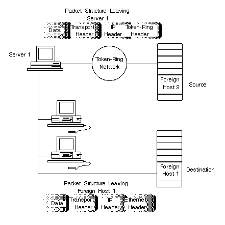
When a foreign host or gateway routes an IP packet to its destination through a single VINES server equipped with TCP/IP Routing, the IP packet is not encapsulated in a VINES IP packet.
When Foreign Host 2 in Figure 5-9 sends an IP packet to Foreign Host 1, the packet passes through Server 1, which strips off the Token-Ring header and attaches an Ethernet header. IP handles the packet through its entire trip.
However, when an IP packet has to pass through two or more VINES servers on its way to the destination, the IP packet is encapsulated in a VINES IP packet. VINES handles the routing for all IP and VINES IP packets that travel between VINES servers. Figure 5-10 shows this process.
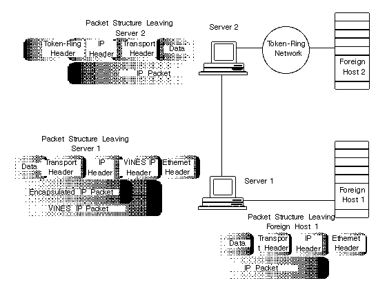
Figure 5-10 illustrates the following process:
1. The packet leaves Foreign Host 1 as an IP packet.
2. When the packet arrives at Server 1, the IP packet is encapsulated in a VINES IP packet (that is, a VINES header is added).
3. The packet is routed through VINES to Server 2.
Note: When encapsulated, the IP packet is treated as user data in the VINES IP packet.
4. When the packet arrives at Server 2, the VINES IP header is stripped off.
5. The packet is routed to its destination through IP.
While encapsulated in VINES IP packets, the IP packets are routed from server to server just like normal VINES packets. When the IP packet reaches a server that must route it to a foreign host or gateway, VINES IP software unencapsulates the packet (strips off the VINES header), and passes it to IP software. Once unencapsulated, the packet becomes a standard IP packet.
PC/TCP To communicate with foreign hosts in a TCP/IP environment, workstations in a VINES network can run PC/TCP or other third-party TCP/IP packages. Workstations running PC/TCP require the services of a server equipped with TCP/IP Routing. VINES supports two versions of PC/TCP:

Workstations running the VINES transport version of PC/TCP can reside anywhere in a VINES network. 
Workstations running the Ethernet-only version must be on the same LAN as a VINES server running TCP/IP Routing, or a foreign host gateway.
For workstations running the VINES transport version of PC/TCP, one server equipped with the TCP/IP Routing provides routing services in most cases. The server must have a unique IP address assigned to the VINES interface, since workstations access the server through VINES. The workstations must be assigned an address in the same network as the one specified for the VINES interface.
Processes This option integrates IP with VINES IP. Both IP and VINES IP are network-layer protocols that work together to route data. VINES IP and IP in the VINES architecture are in layer 3 of the OSI model.
Hardware TCP/IP Routing supports the following data links:

Ethernet 
IEEE 802.5 Token-Ring 
ProNET-10
LAN cards for these data links must be installed in servers and workstations that use this option.
Views Administrators configure TCP/IP Server-to-Server using the TCP/IP configuration menus. Access these menus from the Managing Communications option of the Operator Menu on the server console.
APIs None.
See The Banyan TCP/IP Guide contains a detailed discussion of how this option works, as well as how to install and manage it. The VINES Protocol Definition discusses the VINES IP protocol.
TCP/IP Server-to-Server Option
Description The TCP/IP Server-to-Server option lets a server route VINES packets to VINES destinations through foreign host gateways. It also lets a server handle VINES packets that the foreign host gateways route to it.
Client Support No application client resident on network workstations.
Features Servers equipped with TCP/IP Server-to-Server can exchange VINES packets through foreign host gateways, which perform IP routing functions. VINES packets contain data that originates from VINES applications, such as mail and the StreetTalk naming service.
Example Routing Packets Using TCP/IP Server-to-Server
In Figure 5-11, Server 2 can route VINES packets to Server 1 through Foreign Host Gateway 1. Server 2 also can handle VINES packets that Foreign Host Gateway 1 routes to it.
Notice that some servers need both Banyan TCP/IP options installed. Server 2 has to route IP packets between Foreign Host 2 and Foreign Host 3 and also routes VINES traffic through Foreign Host Gateway 1.
If your server has TCP/IP Server-to-Server installed, it must know the IP addresses and names or serial numbers of servers that are running the same option and reside in other VINES networks. The other VINES networks can be reached through foreign host gateways only.
Encapsulating Packets Like TCP/IP Routing, the Server-to-Server option also performs encapsulation. When a server equipped with TCP/IP Server-to-Server routes a VINES packet through a foreign host gateway, VINES IP software passes the packet to IP software. The IP software encapsulates the VINES IP packet in an IP packet.
Example TCP/IP Server-to-Server Packet Encapsulation
Figure 5-12 illustrates the following steps:
1. Workstation 1 sends a VINES packet to Server 1.
2. Server 1 encapsulates the VINES packet in an IP packet and routes the packet to Foreign Host Gateway 1.
3. Foreign Host Gateway 1 routes the packet to Server 2.
4. Server 2 strips off the IP header and routes the remaining VINES IP packet to Workstation 2.
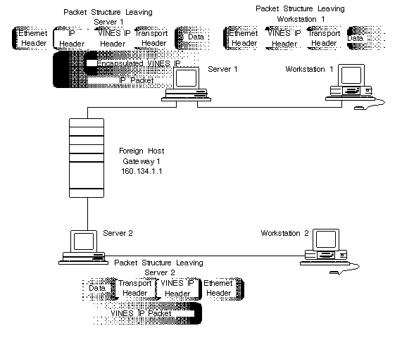
When a server sends a VINES IP packet, the packet contains the VINES IP address of its destination. If that destination can be accessed only through foreign host gateways, a server equipped with TPC/IP Server-to-Server must map the VINES IP address of the destination to an IP address. This IP address is placed in the IP header that encapsulates the VINES IP packet and is used by hosts to route the packet through the IP backbone.
IP Backbone A server does not always need the TCP/IP option installed to participate in a TCP/IP network. In most cases, a server needs the TCP/IP option installed only if it is on the IP backbone. The IP backbone is the interconnected pattern of gateways and the physical media that link them. Think of the IP backbone as the major highway in the network, and gateways as entrances onto that major highway.
Example IP Backbone
Figure 5-13 shows a sample IP backbone. Server 1, Server 2, and the Foreign Host Gateway are on the IP backbone, and implement IP. Server 3 routes VINES packets to and from the two workstations connected to it, but does not need to implement IP. Server 3 uses the services of Server 1 to route VINES packets through the IP backbone.

Processes This option integrates IP with the VINES Internet Protocol (VINES IP). Both IP and VINES IP are network-layer protocols that work together to route data.
Hardware The TCP/IP Server-to-Server option supports the following data links:

Ethernet 
IEEE 802.5 Token-Ring 
ProNET-10
Install LAN cards for these data links in servers and workstations that use this option.
Views Administrators configure TCP/IP Server-to-Server using the TCP/IP configuration menus. Access these menus from the Managing Communications option of the Operator Menu on the server console.
APIs Developers can use server-based TCP/UDP sockets to develop applications.
See The Banyan TCP/IP Guide contains a detailed discussion of how this option works, as well as how to install and manage it. The VINES Protocol Definition discusses the VINES IP protocol. The VINES TCP/UDP Programming Interface discusses developing applications.
Description The Token-Ring Bridge option lets your server emulate an IBM computer that runs the IBM Token-Ring Network Bridge program. The option lets VINES or non-VINES systems on different Token-Ring LANs communicate through the server.
Note: The Banyan Token-Ring Bridge option emulates only IBM local Token-Ring bridges. It does not emulate remote bridges.
A Token-Ring bridge connects two Token-Ring LANs. A Token-Ring LAN is a group of nodes directly connected in a ring topology by a common physical medium. The nodes use MAC sublayer protocols that conform to the IEEE 802.5 standard to communicate. A Token-Ring LAN is also called a ring. Examples of Token-Ring bridges include an IBM computer equipped with the IBM Token-Ring Network Bridge Program or another computer that emulates one.
Client Support No application client resident on network workstations.
Features The VINES Token-Ring Bridge option lets your VINES server emulate an IBM computer that runs the IBM Token-Ring Network Bridge Program. The option lets end nodes that reside on different Token-Ring LANs communicate through your server. End nodes are computers that require the routing services of a Token-Ring bridge to communicate with each other when they are connected to different Token-Ring LANs. Examples of end nodes are IBM hosts, IBM 3174 cluster controllers, and VINES servers.
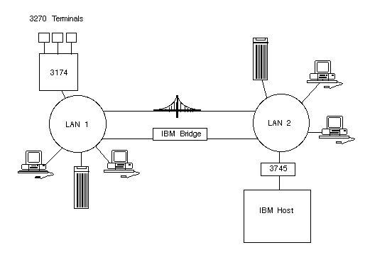
Figures 5-14, 5-15, and 5-16, demonstrate three different ways to connect Token-Ring bridges to LANs.
Figure 5-14 shows a VINES server that connects two Token-Ring LANs. The server is equipped with the Token-Ring Bridge option. The server supports Systems Network Architecture (SNA) communications between an IBM host on one LAN and an IBM 3174 cluster controller on the other.

Figure 5-15 shows a network with multiple bridges and Token-Ring LANs. Multiple Token-Ring bridges can connect more than two Token-Ring LANs, forming a network in which end nodes on one LAN can reach end nodes on any other LAN.
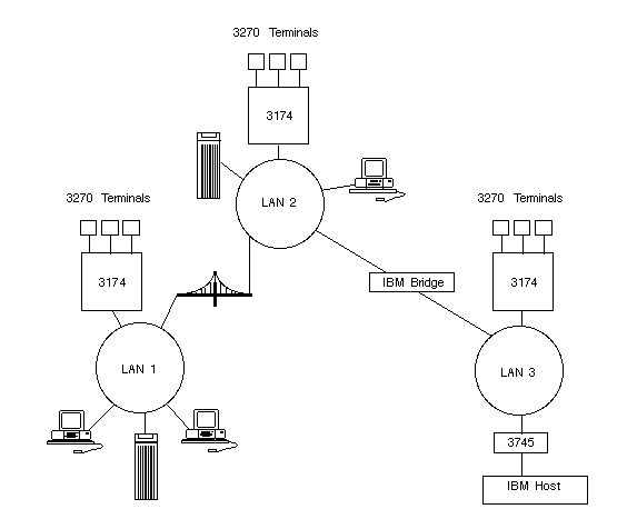
Figure 5-16 shows a network with two Token-Ring LANs connected by an IBM Token-Ring bridge and a VINES server equipped with the Token-Ring Bridge option. When a large amount of network traffic passes between two LANs, this type of configuration helps distribute the routing workload between the bridges. The routing workload might not be distributed evenly between the bridges.
Disabling Bridging The Token-Ring Bridge option lets you enable and disable the bridging capability on the server. To act as a Token-Ring bridge, bridging must be enabled for each of the server's Token-Ring cards. If you disable bridging for one card, you disable bridging for all cards.
When bridging is disabled, the Token-Ring cards can still send Token-Ring packets that originate from the server, and can receive Token-Ring packets that are destined for the server.
You may want to disable the bridging capability when problems occur, such as network traffic congestion, or if you no longer want the server to act as a bridge.
Hop Count The Token-Ring bridge software uses this parameter to determine the number of hops that all-routes and single-route broadcast packets can travel. Each Token-Ring bridge through which a Token-Ring packet passes counts as one hop. The hop is counted as soon as the Token-Ring card in the Token-Ring bridge receives the packet. The maximum number of hops is seven.
3270/SNA and Token-Ring 3270/SNA services on your server can communicate with IBM hosts over a Token-Ring LAN. These services use the same Token-Ring cards that you configure for the Token-Ring Bridge option. When a 3270/SNA service and the Token-Ring Bridge option share the same card, you must configure the maximum packet size and number of transmit buffers parameters to meet both 3270/SNA and Token-Ring Bridge option requirements.
Source Routing VINES Source-level Routing protocols (SLR) support IBM protocols used to connect workstations and servers in networks that have Token-Ring LANs connected by IBM Token-Ring bridges. VINES 5.5 and higher support both local and remote Token-Ring Bridges. See Chapter 3 for more information on VINES SLR.
Processes To communicate across Token-Ring bridges, end nodes on the Token-Ring LANs must perform source-level routing. When one end node sends data to another end node through a Token-Ring bridge, the source end node must include up to 18 bytes of special routing information with the data. This information is called source-level routing information. Data is forwarded in one of two ways:

If the destination end node resides on one of the LANs to which the bridge is connected, the bridge uses the source-level routing information to forward the data directly to the destination end node. 
If the destination end node and the bridge are not directly connected, the bridge uses the source-level routing information to forward the data to another bridge. The data is eventually delivered to the destination end node.
VINES servers and workstations perform source-level routing. They must have this capability enabled under certain conditions. See the VINES Token-Ring Bridge Option Guide for more information.
Hardware One of the following Token-Ring cards is required:

IBM Token-Ring Adapter II 
IBM Token-Ring 16/4 Adapter 
IBM Token-Ring Adapter/A 
IBM Token-Ring 16/4 Adapter/A
Views Administrators add the service to the server and configure it from the Configure/Diagnose Server option. This option is found in the System Maintenance menu of the server console's Operator Menu.
Users configure their workstations for Token-Ring LAN cards by selecting the card type in the VINES PCCONFIG menu.
APIs None.
See Managing Communications and VINES Token-Ring Bridge Option Guide.
Description The VINES X.25 option lets a server use the X.25 packet switching protocol to communicate through a private or public data network (PDN), through an Integrated Services Digital Network (ISDN), or directly with other servers and host computers.
Client Support No application client resident on network workstations.
Features X.25 consists of a user interface to X.25 and the X.25 software. Figure 5-17 describes how X.25 is implemented in VINES.

VINES X.25 has two categories of "users," those who use the VINES Applications Toolkit and those who use VINES configuration programs. Third-party applications, X.29 dial-in, and X.29 host communications access X.25 by means of the toolkit.
X.25 server-to-server connections use the VINES interface. VINES configuration programs set up and clear an X.25 connection. Once the connection is established, it is seen as another interface to VINES.
Supported Facilities The following list summarizes the facilities that VINES implements:

Nonstandard default window sizes 
Nonstandard default packet sizes 
Flow control parameter negotiation 
One-way logical channel outgoing 
One-way logical channel incoming 
Closed User Group (CUG) 
Closed user group with outgoing access 
Reverse charging acceptance 
Bilateral closed user group 
Closed user group selection 
Per call facilities 
Closed user group selection 
Reverse charging 
Flow control parameter negotiation 
Call redirection notification 
Call line address modification notification 
Closed user group with outgoing access selection 
Bilateral closed user group
Limitations The VINES X.25 option has the following limitations:

A VINES server supports a maximum of 256 virtual circuits. This limit applies to all server platforms. 
The ICA card is the only serial communications card that the option supports. It supports a maximum of 128 virtual circuits. 
An ICA card has a maximum of two X.25 lines. 
An X.25 line supports a maximum of 32 Permanent Virtual Circuits (PVCs).
Network Connections VINES X.25 options support the following connections:

Server-to-server connected through a PDN 
Server-to-server directly connected 
Server to host through a PDN 
Workstation to server connections through a PDN 
Workstation to server connections through an ISDN network 
Workstation to server connections over a switched line 
Server-to-server, server-to-host, DOS workstation-to-server through Permanent Virtual Circuits (PVC) and Switched Virtual Circuits (SVC)
Processes There are two separate code paths into the X.25 protocol driver. The driver handles all the protocol-specific messages to and from the VINES ICA, ICAmC, or ICAplus cards. The ICA driver handles the exchange of messages between the ICA and the VINES server. X.25 packet and frame level software resides on the ICA card.
Hardware Install an ICA card in the server to support this option.
Views After connecting a line to the serial communications card, you must specify certain information at the server console to enable the line. You must also provide parameters that you obtained from the PDN or the telephone company providing the ISDN service. This is done from the Managing Communications menu accessed through the server console's Operator Menu.
APIs The VINES Applications Toolkit includes special socket calls that support X.25 communications.
See VINES X.25 Guide for general information and the VINES X.25 Programming Interface for information on functions.
Description The VINES X.29 option supports two types of communications:

X.29 Dial-in lets multiple DOS workstation users dial in to a VINES network over an X.25 line. 
X.29 host communications lets a user of VINES Asynchronous Terminal Emulation access a host computer over an X.25 line.
Client Support Workstations running DOS and Windows. Also accessible through OS/2 DOS-mode windows.
Features The X.29 option lets a VINES server communicate with a host directly over an X.25 line or through a Public Data Network (PDN). These connections require the X.25 server-to-server option and the Asynchronous Terminal Emulation option.
The X.29 option also lets a DOS workstation dial in to a VINES server through a PDN or Integrated Services Digital Network (ISDN) service. This requires the X.25 server-to-server option.
Workstation Connections Workstations use X.29 Dial-in software to connect to the VINES network through a server equipped with the X.29 option. The workstation and the X.29 server can be connected by one of the following ways:

A telecommunications network that provides Integrated Services Digital Network (ISDN) services 
An X.25 Public Data Network (PDN) 
Your company's private X.25 network 
Your own X.25 packet assembly equipment and a switched telephone company line, using traditional voice-grade, analog communications
PDNs To communicate through an X.25 PDN or a switched point-to-point telephone company line, the workstation requires a modem and should have access to a Packet Assembler/Disassembler (PAD). The PAD may be either remote or local.
Figure 5-18 shows a sample network topology in which three users at DOS workstations access a VINES network through an X.25 PDN and an X.29 server.
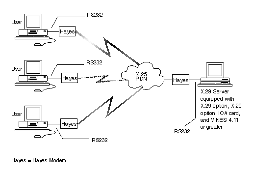
In this figure, the DOS workstations dial a PAD at the PDN. The PAD accepts the asynchronous characters from the DOS workstations and assembles them into packets.
ISDNs Where workstations and servers are connected by ISDN networks, the workstations use D-Channel packets and the servers use B-Channel packets without requiring special equipment. The D-Channel packets are cost-effective.
For the server to use D-Channel packets, the server must be equipped with a special device called a DISNII. This device is available from AT&T. Note that D-Channel communications cost less than B-Channel communications, but D-Channels provide slower throughput than B-Channels. In ISDN networks, X.29 Dial-in is certified to work with AT&T 5ESS and compatible data switches.
Figure 5-19 shows a sample network topology in which three workstation users access a VINES network through an ISDN network.
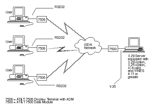
The 7506 accepts asynchronous characters from the DOS workstation and assembles them into X.25 packets for transmission to the server.
Hardware The hardware requirements differ for ISDN and PDN connections. When using an ISDN network, the workstation requires the following equipment:
|
|
An AT&T ISDN terminal adapter (TA), such as the AT&T ISDN 7505 Modular Terminal or an AT&T ISDN 7506 Display Terminal. TAs are telephone-like devices AT&T TAs require an ISDN Asynchronous
Data Module (ADM). The TA that you use must be equipped with
this module, which lets the TA support simultaneous voice and
data communications. |
|
|
Your telephone company must provide DOS workstation users with access to an AT&T ISDN switch. The workstation uses this switch to connect to the X.29 server. The DOS workstation transmits data to and receives data from the AT&T switch at speeds of up to 19.2 Kbps. The server transmits data to and receives data from the switch at speeds of up to 64 Kbps if a high-speed line on the ICA card is used, or 19.2 Kbps if a slow-speed line is used. The speed at which the server transmits data to and receives data from the switch should be much higher than the speed at which the workstation transmits data to and receives data from the switch. For example, if the server supports a speed of 56 or 64 Kbps, the workstation should support a speed of 19.2 Kbps. In another example, if the server supports a speed of 19.2 Kbps, the workstation should support a speed of 9600 bps. |
When using PDN or a switched point-to-point telephone company line, the workstation requires the following:

Modem 
PAD
To communicate with workstations, the X.29 servers must have the following equipment:

An ICA, ICAmC, or ICAplus card. The X.25 line that the server uses for X.29 Dial-in communications connects to this card. 
A modem, if communication is through an X.25 PDN or over a switched point-to-point telephone line. 
An AT&T 7500 Data Module or compatible model, if communication is through an ISDN network. To connect the X.25 line to the 7500 Data Module, use either the V.35 adapter that AT&T provides or the BanyanV.35 adapter.
Views Administrators must do the following:
|
|
Select an appropriate server for X.29 Dial-in communications. |
|
|
Prepare the server for X.29 Dial-in communications. |
|
|
Set up the X.29 Dial-in connection. |
|
|
Set up the necessary telecommunications equipment. |
|
|
Evaluate server security features for X.25 lines that support X.29 Dial-in communications. |
APIs None.
See VINES X.29 Dial-in Guide and Banyan Asynchronous Terminal Emulation Guide.